
Enables AI agents to automate SolidWorks CAD tasks including creating parts, assemblies, drawings, and managing mates via the COM API.
Also known as andrewbartels1/SolidworksMCP-python, solidworksmcp-python, solidworks-mcp-python
- Stars
- 99
- Tools
- —
- Downloads, 30 days
- —
- Latest version
- 2.0.0
- Last commit
- Nov 13, 2026
- License
- MIT
What is SolidWorks MCP?
SolidWorks enables AI agents to automate SolidWorks CAD tasks including creating parts, assemblies, drawings, and managing mates via the COM API.
Summary generated from the project's README
About SolidWorks MCP server
Automating CAD workflows by describing mechanical parts and assemblies in plain English is what this server enables for engineers and developers. It provides a bridge between AI agents and SolidWorks by wrapping the COM API into 156 specialized MCP tools. These tools allow an agent to execute complex sequences like sketching, extruding, adding dimensions, and managing mates to build functional mechanisms.
Users can interact with the server through an MCP client like Claude Code or use the underlying Python interface for direct scripting. The server is designed for Windows environments and has been tested on SolidWorks 2026. Because the tools are categorized by support levels—stable, beta, experimental, or planned—the AI agent can intelligently determine the reliability of a specific command before attempting a task. This structure supports everything from creating single parts to generating complete drawing packages with bills of materials.
What you can do with it
- 1Build complex mechanisms from textAn engineer can provide a detailed description of a multi-part mechanism to have an AI agent construct all parts and assemblies.
- 2Generate dimensioned drawing packagesA developer can request a fully dimensioned drawing including a bill of materials based on a simple part specification.
- 3Automate CAD via Python scriptsDevelopers can use the provided adapters to run asynchronous Python calls for CAD automation without needing an AI agent.
Written from the project's README. Every use case is checked against a quote from it.
How to install SolidWorks MCP
Formats verified 10 Nov 2026Install SolidWorks MCP in Claude Code
$ claude mcp add solidworksmcp-python -- uvx solidworks-mcp-pythonInstall SolidWorks MCP in Cursor
~/.cursor/mcp.json
{
  "mcpServers": {
    "solidworksmcp-python": {
      "command": "uvx",
      "args": [
        "solidworks-mcp-python"
      ]
    }
  }
}Install SolidWorks MCP in VS Code
.vscode/mcp.json
{
  "servers": {
    "solidworksmcp-python": {
      "type": "stdio",
      "command": "uvx",
      "args": [
        "solidworks-mcp-python"
      ]
    }
  }
}Install SolidWorks MCP in Claude Desktop
claude_desktop_config.json
{
  "mcpServers": {
    "solidworksmcp-python": {
      "command": "uvx",
      "args": [
        "solidworks-mcp-python"
      ]
    }
  }
}Install SolidWorks MCP in Codex
~/.codex/config.toml
[mcp_servers.solidworksmcp-python]
command = "uvx"
args = ["solidworks-mcp-python"]
Install SolidWorks MCP in Gemini CLI
~/.gemini/settings.json
{
  "mcpServers": {
    "solidworksmcp-python": {
      "command": "uvx",
      "args": [
        "solidworks-mcp-python"
      ]
    }
  }
}Automated checks
Ran Nov 12, 2026Full report →Passed our automated checks. That is not a security audit: read the code and give the server the narrowest access it needs. How checks work

- Source repository linked and reachablePass
- Open source license (OSI)Pass
- Commit or release in the last yearPass
- Package name not close to a popular packagePass
- Remote endpoint uses HTTPSNot checked
- Destructive tools are labelledNot checked
- No hidden instructions to the modelPass
- No critical advisory in the package or its dependenciesPass
README
View on GitHubSolidWorks CAD Assistant & MCP Server





Python MCP server for SolidWorks automation with 156 tools, plus an optional agent/prompt-testing layer for AI-assisted workflows.
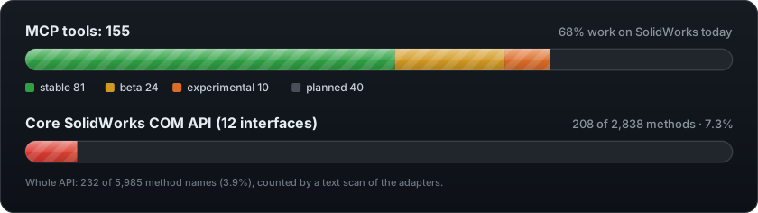
Generated from the code; click it for every tool, its level and why, filterable by level and family.
Two tools in one
-
A Python interface for scripting SolidWorks. The adapters wrap SolidWorks' COM API in plain
asyncPython calls, so you can automate it from your own scripts without an AI in the loop:from solidworks_mcp.adapters.base import ExtrusionParameters from solidworks_mcp.adapters.pywin32_adapter import PyWin32Adapter adapter = PyWin32Adapter({}) await adapter.connect() await adapter.create_part() await adapter.create_sketch("Top") await adapter.add_rectangle(-20, -10, 20, 10) # mm await adapter.exit_sketch() await adapter.create_extrusion(ExtrusionParameters(depth=10)) -
An MCP tool server on top of it. The same calls, exposed as 156 MCP tools, so an agent such as Claude Code can build parts, assemblies and drawings from a description. Each tool carries a support level (stable, beta, experimental or planned), so the agent knows how far to trust it.
See it work
A whole mechanism from a description
I took SolidWorks' own U-Joint sample, read every part, sketch, feature and mate, and wrote it up as a plain-English prompt: eight parts, a crank sub-assembly, and a main assembly that has to move like a real joint. Then Claude Code (Opus 5.5, medium effort) built it from that prompt alone.
I want to build a small hand-cranked universal joint in SolidWorks: eight parts, a crank sub-assembly, and the main assembly. It's a mechanism: turning the knob turns the crank, which drives the joint through an angle, so the assemblies must still move the way described in sections 9 and 10. Please reason through each part before you start drawing, check every part once it's built, and tell me if something can't be done with the tools rather than guessing. All sizes are in millimetres (the original was drawn in inches, so the numbers are odd). SolidWorks' Y axis is up. Save every part and both assemblies in this folder, with the names given below.
1. bracket.SLDPRT: a bent plate, 6.35 mm thick and 38.1 mm wide. Seen from the side (sketch on the Right plane, Y up, Z towards the front), the inside outline of the bend is an open chain:
- a back wall going straight up 82.55 mm from the origin;
- from its top, a top arm going forward 57.15 mm;
- from the origin, a bottom foot going forward 44.45 mm;
- from the front of the foot, a lip rising at 40° for 42.77 mm (it ends 27.49 mm up and 77.22 mm forward). The 6.35 mm thickness is on the outside of that outline: above the top arm, behind the back wall and under the foot. The 38.1 mm width is centred on the Right plane. Drill a 12.7 mm hole straight down through the top arm and on through the foot below it (one cut, both plates), centred across the width and 38.1 mm forward of the back wall's inside face.
2. Yoke_male.SLDPRT: a fork with a stub shaft.
- Start with a 38.1 mm diameter cylinder, 47.625 mm tall, standing on the Top plane.
- Its bottom becomes a fork with two ears. Each ear is 19.05 mm wide and 8.89 mm thick, and the gap between them is 20.32 mm, centred. Each ear has a rounded end: a full radius of 9.525 mm, centred 9.525 mm above the bottom. Where an ear meets the solid part of the cylinder, round the shoulder with a 9.525 mm radius, so the solid part starts 29.21 mm above the bottom.
- Drill a 9.525 mm cross hole through both ears at the centre of their rounded ends, square to the ears.
- On top, add a 12.7 mm diameter stub, 19.05 mm tall, on the cylinder's axis. Chamfer its top edge 1.27 mm at 60°.
- Cut a flat on the stub, 12.7 mm long down from its top. The flat is 4.7625 mm from the axis, so it is 1.5875 mm deep.
3. Yoke_female.SLDPRT: the same 38.1 x 47.625 mm cylinder with the same fork and the same cross hole as the male yoke, but no stub. Instead, a 9.525 mm hole goes all the way through along its axis.
4. spider.SLDPRT: a 19.05 mm cube centred on the origin. It has two 9.525 mm holes, both through its centre: one front to back, and one left to right.
5. pin.SLDPRT: a 9.398 mm diameter rod, 38.1 mm long.
6. crank-shaft.SLDPRT: a 12.573 mm diameter shaft, 40 mm long, standing on the Top plane.
- Around its bottom 15.875 mm, a collar 18.923 mm in diameter.
- A 4.763 mm fillet where the collar meets the shaft, and a 4.763 mm fillet on the collar's top outer edge.
- In the bottom, a D-shaped socket 12.7 mm deep. It is a 12.954 mm circle with a flat 4.889 mm from the axis, to take the male yoke's stub.
- A 2.381 mm cross hole through the collar wall, square to the socket's flat and 6.35 mm up from the bottom.
- At the top, a matching flat 6.35 mm long, 4.889 mm from the axis.
- A 0.794 mm x 45° chamfer on the top end.
7. crank-arm.SLDPRT: a flat bar, 75 x 19.05 x 6.35 mm.
- Near one end, a 12.7 mm D-hole centred 9.525 mm from the end and on the bar's centreline. Its flat is 4.889 mm from the hole's centre, towards that end. It fits the shaft's top flat.
- Near the other end, a 4.763 mm hole 9.525 mm from that end, also on the centreline.
8. crank-knob.SLDPRT: a mushroom-shaped knob, revolved 360° about the vertical axis. Going up from the bottom, its profile has:
- a 4.572 mm diameter shank, 6.35 mm long;
- a step out to a 9.525 mm diameter;
- a concave quarter-round of radius 6.35 mm that flares out to 22.225 mm diameter, 12.7 mm up;
- a convex half-round of radius 4.7625 mm that reaches 31.75 mm diameter at its widest;
- a flat top 22.225 mm in diameter, 22.225 mm above the bottom.
9. crank sub.SLDASM:
- The crank shaft is fixed.
- The crank arm's D-hole goes on the shaft's top flat: the hole is concentric with the shaft, the flats are parallel, and the arm sits on the shoulder where the flat starts. The flats lock the arm to the shaft, so they turn together.
- The knob's shank goes into the arm's small hole, with the knob's step resting on the arm's top face. The knob stays free to spin in its hole, like a handle.
10. UJoint.SLDASM:
- The bracket is fixed.
- The male yoke hangs under the bracket's top arm. Its stub goes up through the bracket's hole (concentric), and the top of its cylinder is flat against the underside of the arm. It must stay free to turn in that hole.
- The spider sits centred between the male yoke's ears, with one of its holes lined up with the ears' cross hole. It pivots on that axis.
- The female yoke's ears go around the spider's other hole, centred on the spider. Its top face is parallel to the bracket's sloped lip, so its axis points down and forward. It pivots on the spider and turns about its own axis.
- Put one pin through the male yoke's ears and the spider, and one pin through the female yoke's ears and the spider. Each pin's ends are flush with its yoke's round outside, and each pin turns with its yoke.
- Insert the crank sub-assembly. Its shaft's D-socket goes over the male yoke's stub: concentric, with the flats parallel, and the bottom of the shaft 1 mm above the top of the bracket. The flats lock the crank to the male yoke.
- The result should be a mechanism with one free motion: turning the knob around the crank shaft's axis turns the male yoke, the spider rocks on its pins, and the female yoke turns about its tilted axis. Choose mates that leave exactly those rotations free and lock everything else.
When it's all built, check each part's size and the assembly's component and mate counts, say which rotations your mates leave free, and tell me what you couldn't do.
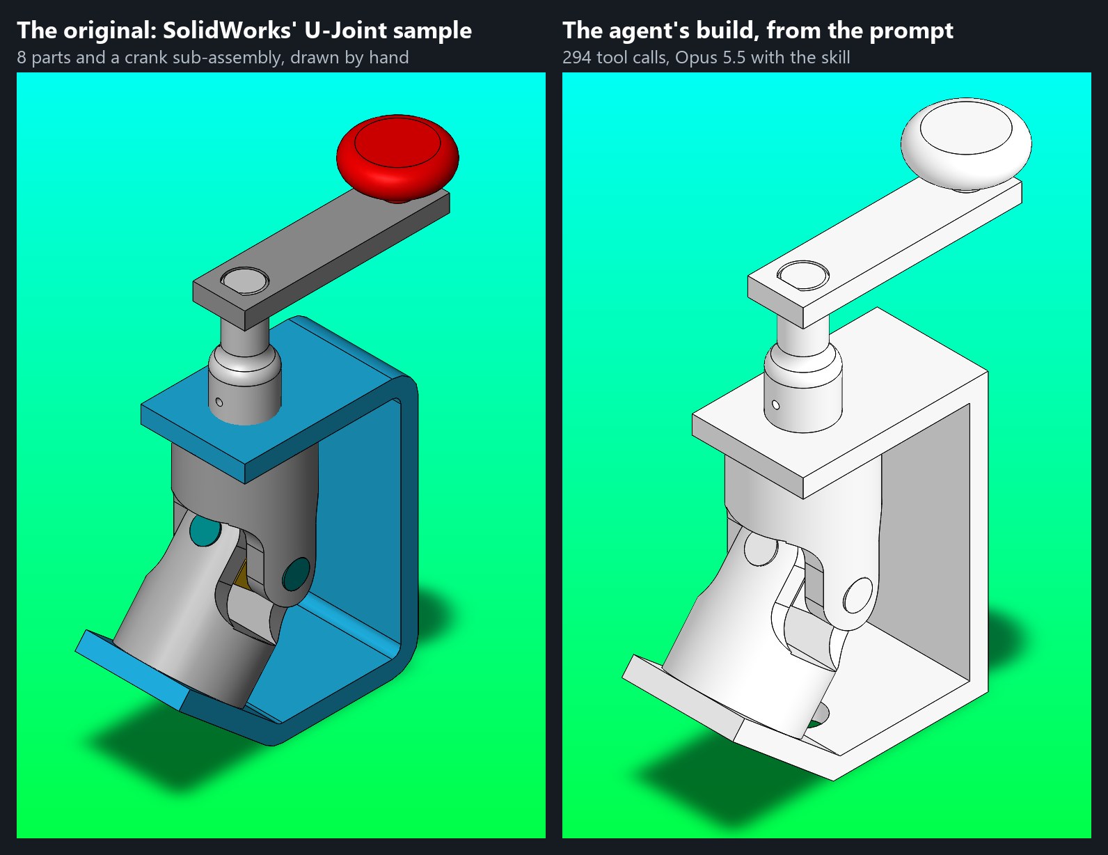
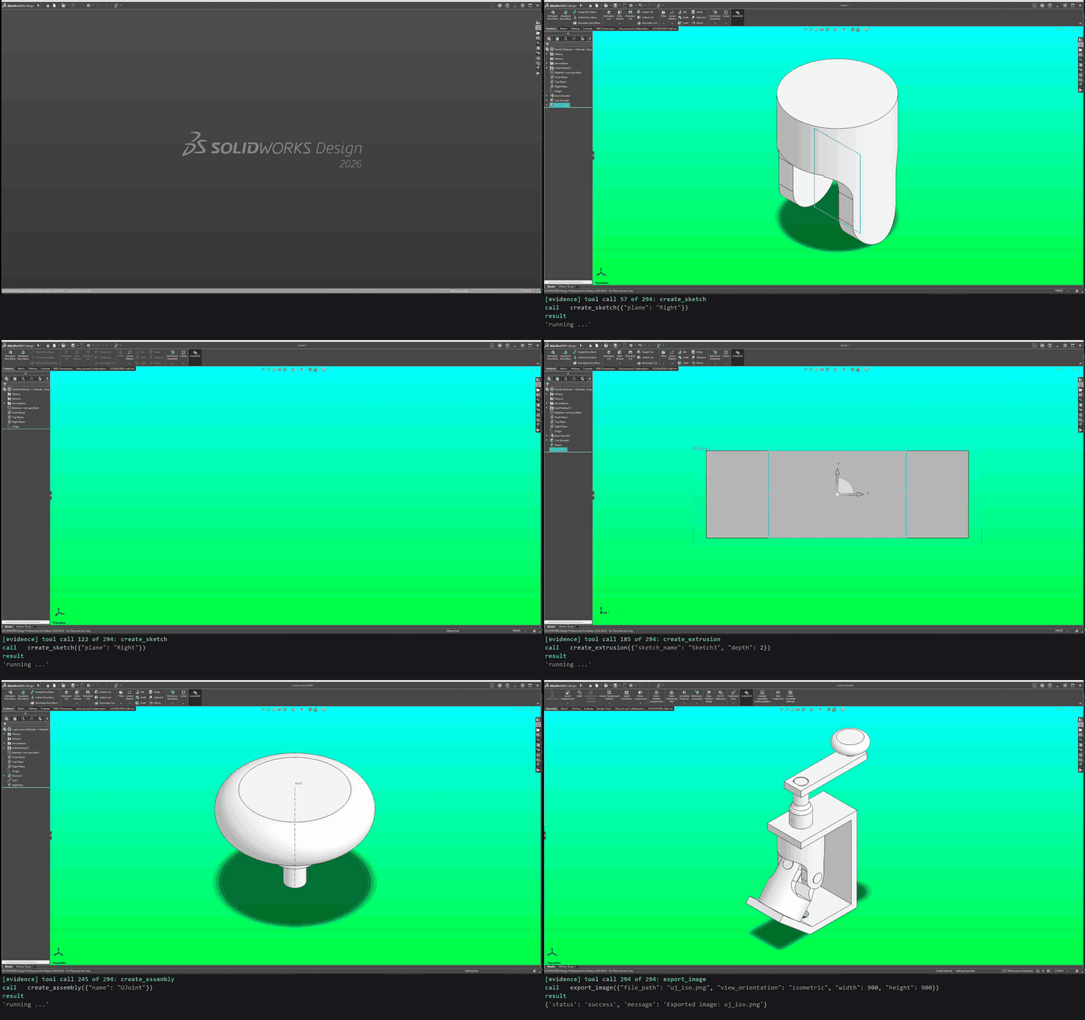
Six of the eight parts match the sample's volume within 0.2 %, and all eight within 1 %. The mates leave the mechanism free to turn. The recording replays the session's 294 calls (sped up 80 times). The walkthrough has the prompt, the part-by-part comparison, and what the agent couldn't do. The same prompt run with and without the agent skill made the same parts, which is why I want skills that improve results (#207).
A drawing package from one prompt
Make a 100 x 50 x 10 mm AISI 1020 mounting plate with four M5 clearance holes, 10 mm in from each edge, and draw it fully dimensioned. Stack two of them 10 mm apart, check the result, and draw the assembly with a BOM.
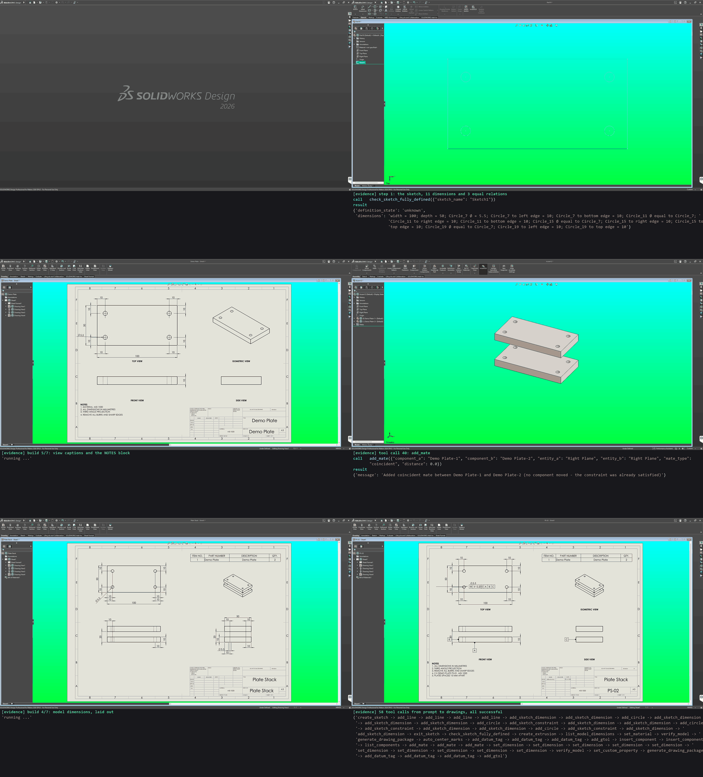
The 58 tool calls an agent made from that prompt, run against SolidWorks 2026 through the same MCP tools a client calls, and recorded (sped up five times). Each result is checked against a hand calculation: the plate's volume and mass, the 10 mm gap and the BOM quantity. This is a replay of the calls, not a recorded model session.
Note: the demo is not perfect, and is not the most efficient way to get this result. The run pauses after each call so it can be read, and the calls are chosen to show what the tools can do: every sketch dimension is added one at a time, and the mate distance is stepped down only so the plates are seen coming together.
The walkthrough in the docs has the agent's plan and every call with its arguments. Run it yourself with the README demo; the calls are also in plate_stack_calls.json.
- Sketch (24 calls):
create_sketchon Top; fouradd_linefor the 100 x 50 outline;add_circlefor each Ø5.5 hole;add_sketch_dimensionfor the 100, the 50, one Ø5.5 and each hole 10 mm from two edges;add_sketch_constraintmaking the other three holes equal;exit_sketch - Check and extrude:
check_sketch_fully_defined,create_extrusion10 mm (+49 049.7 mm³ read back) - Material and check:
list_model_dimensions(finds the Ø5.5 by value),set_materialAISI 1020,verify_model(volume, mass 0.3875 kg, size, 1 feature, 1 body) - Plate drawing:
generate_drawing_packagePS-01 (A3, four views, every model dimension laid out with no overlaps, notes, title block, PDF),auto_center_marks - GD&T:
add_datum_tagA, B and C, thenadd_gtol⊕ Ø0.2 Ⓜ A|B|C on the Ø5.5 - Assembly:
insert_componenttwice,list_components,add_mateFront and Right coincident and Top planes 60 mm apart,set_dimensionstepping that distance down to 20 mm (10 calls),verify_model(2 parts, 3 mates, no interference; the stack measures 30 mm, so the gap is 10 mm) - Assembly drawing:
set_custom_propertyMaterial,generate_drawing_packagePS-02 withinclude_bom(the BOM above the isometric: Demo Plate, QTY 2), then the same datums and position frame
Overview
Tried it? Tell us what worked and what didn't in a feedback issue. Reports from real setups decide what gets fixed next.
This project focuses on practical SolidWorks automation with an AI-friendly loop:
- describe intent
- generate a plan
- execute MCP tools
- inspect results
- iterate
It includes:
- core MCP runtime for SolidWorks tool execution
- COM/VBA routing and adapter safety wrappers
- tool coverage across modeling, sketching, drawing, analysis, export, automation, templates, and macros
- optional agent orchestration/testing utilities under
src/solidworks_mcp/agents/
Demos
Each GIF is a live test driving SolidWorks 2026 through the MCP tools, with the call and its result captioned beneath. Click one to see what it checks, a prompt that asks for it, and its tool calls.
See every demo in the docs: what each one shows, its prompt, every tool call with its arguments (all 58 for the demo at the top), and how to run them yourself.
Supported Today
- Windows + SolidWorks COM automation for the main CAD lifecycle.
- Tested on SolidWorks 2026. Earlier versions may work but are untested. To check yours, run
uvx solidworks-mcp-python selftestwith SolidWorks open, then send the result with the compatibility report form. The compatibility page lists the releases checked so far. - Modeling, sketching, drawing, analysis, export, automation, templates, and macro tools.
- Every tool's support level, and the reason a tool isn't stable yet, is on the progress page.
Not Yet / Simulated
- Mock adapter output is simulated and should not be treated as engineering truth.
- Live 3D viewport streaming in a UI.
- Checkpoint-level interference validation.
- Simple simulation and fluid workflows
- Simple Topology Optimization via SimulationXpress etc.
Install
You need Windows 10 or 11 and SolidWorks (opened at least once). In PowerShell, install uv, then open a new PowerShell window and run setup:
powershell -ExecutionPolicy ByPass -c "irm https://astral.sh/uv/install.ps1 | iex"
uvx solidworks-mcp-python setup
uv fetches Python 3.13 and the server from PyPI by itself; nothing to clone. The guided setup then:
- finds your SolidWorks version and the MCP clients on your PC: Claude Desktop, Claude Code, VS Code, Cursor and LM Studio;
- lets you pick which clients to connect;
- starts the server once to check that it lists its tools (in mock mode, so SolidWorks isn't touched);
- adds a
solidworksentry to each client you picked, then tells you what to restart.
Nothing needs a login or an API key, and the server runs only on your PC. Setup changes only the solidworks entry in each client's config. It backs the file up first and never shows or changes your other servers. Other entries that start this server the old way (run-mcp.ps1 and the like) are offered for removal, so tools don't load twice.
To check it worked: open SolidWorks, restart your client, and ask "What model is open in SolidWorks?"
The package is solidworks-mcp-python. uvx solidworks-mcp installs a different project. To work on the server itself, install from a clone. More fixes are in Troubleshooting.
SolidWorks MCP questions
How do I add SolidWorks MCP to Claude Code?
Run claude mcp add solidworksmcp-python -- uvx solidworks-mcp-python in your terminal. Add --scope user to make it available in every project.
How do I add SolidWorks MCP to Cursor?
Open ~/.cursor/mcp.json and add the server under mcpServers, using the Cursor config shown in the install section above.
What can this server do with SolidWorks?
It allows AI agents to build parts, assemblies, and drawings from text descriptions, as well as perform extrusions and manage mates.
Can I use this without an AI agent?
Yes, it provides a Python interface for scripting SolidWorks directly using async Python calls.
How many tools are available?
The server provides 156 MCP tools for SolidWorks automation.