
Позволяет ИИ-агентам автоматизировать задачи CAD в SolidWorks, включая создание деталей, сборок, чертежей и управление сопряжениями через COM API.
Также известен как andrewbartels1/SolidworksMCP-python, solidworksmcp-python, solidworks-mcp-python
- Звёзды
- 99
- Инструменты
- —
- Загрузки, 30 дней
- —
- Последняя версия
- 2.0.0
- Последний коммит
- 13 нояб. 2026 г.
- Лицензия
- MIT
Что такое SolidWorks MCP?
SolidWorks — это MCP server. Позволяет ИИ-агентам автоматизировать задачи CAD в SolidWorks, включая создание деталей, сборок, чертежей и управление сопряжениями через COM API.
Сводка сгенерирована из README проекта
О SolidWorks MCP server
Этот сервер позволяет инженерам и разработчикам автоматизировать рабочие процессы CAD, описывая механические детали и сборки обычным английским языком. Он служит связующим звеном между ИИ-агентами и SolidWorks, оборачивая COM API в 156 специализированных MCP инструментов. Эти инструменты позволяют агенту выполнять сложные последовательности действий, такие как построение эскизов, выдавливание, добавление размеров и управление сопряжениями для создания функциональных механизмов.
Пользователи могут взаимодействовать с сервером через MCP-клиент, например Claude Code, или использовать базовый Python-интерфейс для прямого написания скриптов. Сервер предназначен для сред Windows и протестирован на SolidWorks 2026. Поскольку инструменты разделены по уровням поддержки — стабильные, бета, экспериментальные или запланированные — ИИ-агент может интеллектуально определять надежность конкретной команды перед выполнением задачи. Такая структура поддерживает всё: от создания отдельных деталей до генерации полных комплектов чертежей со спецификациями.
Что вы можете с ним делать
- 1Создание сложных механизмов из текстаИнженер может предоставить подробное описание многокомпонентного механизма, чтобы ИИ-агент сконструировал все детали и сборки.
- 2Генерация комплектов чертежей с размерамиРазработчик может запросить полностью размеченный чертеж, включая спецификацию, на основе простого описания детали.
- 3Автоматизация CAD через Python-скриптыРазработчики могут использовать предоставленные адаптеры для выполнения асинхронных вызовов Python для автоматизации CAD без необходимости использования ИИ-агента.
Взято из README проекта. Каждый вариант использования проверен на соответствие цитате из него.
Как установить SolidWorks MCP
Форматы проверены 10 ноя 2026Установка SolidWorks MCP в Claude Code
$ claude mcp add solidworksmcp-python -- uvx solidworks-mcp-pythonУстановка SolidWorks MCP в Cursor
~/.cursor/mcp.json
{
  "mcpServers": {
    "solidworksmcp-python": {
      "command": "uvx",
      "args": [
        "solidworks-mcp-python"
      ]
    }
  }
}Установка SolidWorks MCP в VS Code
.vscode/mcp.json
{
  "servers": {
    "solidworksmcp-python": {
      "type": "stdio",
      "command": "uvx",
      "args": [
        "solidworks-mcp-python"
      ]
    }
  }
}Установка SolidWorks MCP в Claude Desktop
claude_desktop_config.json
{
  "mcpServers": {
    "solidworksmcp-python": {
      "command": "uvx",
      "args": [
        "solidworks-mcp-python"
      ]
    }
  }
}Установка SolidWorks MCP в Codex
~/.codex/config.toml
[mcp_servers.solidworksmcp-python]
command = "uvx"
args = ["solidworks-mcp-python"]
Установка SolidWorks MCP в Gemini CLI
~/.gemini/settings.json
{
  "mcpServers": {
    "solidworksmcp-python": {
      "command": "uvx",
      "args": [
        "solidworks-mcp-python"
      ]
    }
  }
}Автоматические проверки
Запущено 12 нояб. 2026 г.Полный отчёт →Прошло наши автоматизированные проверки. Это не аудит безопасности: изучите код и предоставьте серверу минимально необходимый доступ. Как работают проверки

- Связанный и доступный исходный репозиторийПройдено
- Open source лицензия (OSI)Пройдено
- Коммит или релиз за последний годПройдено
- Имя пакета не похоже на популярный пакетПройдено
- Удаленная конечная точка использует HTTPSНе проверялось
- Деструктивные инструменты помеченыНе проверялось
- Нет скрытых инструкций для моделиПройдено
- Нет критических уязвимостей в пакете и зависимостяхПройдено
README
Открыть на GitHubSolidWorks CAD Assistant & MCP Server





Python MCP server for SolidWorks automation with 156 tools, plus an optional agent/prompt-testing layer for AI-assisted workflows.
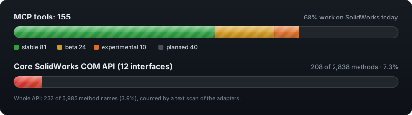
Generated from the code; click it for every tool, its level and why, filterable by level and family.
Two tools in one
-
A Python interface for scripting SolidWorks. The adapters wrap SolidWorks' COM API in plain
asyncPython calls, so you can automate it from your own scripts without an AI in the loop:from solidworks_mcp.adapters.base import ExtrusionParameters from solidworks_mcp.adapters.pywin32_adapter import PyWin32Adapter adapter = PyWin32Adapter({}) await adapter.connect() await adapter.create_part() await adapter.create_sketch("Top") await adapter.add_rectangle(-20, -10, 20, 10) # mm await adapter.exit_sketch() await adapter.create_extrusion(ExtrusionParameters(depth=10)) -
An MCP tool server on top of it. The same calls, exposed as 156 MCP tools, so an agent such as Claude Code can build parts, assemblies and drawings from a description. Each tool carries a support level (stable, beta, experimental or planned), so the agent knows how far to trust it.
See it work
A whole mechanism from a description
I took SolidWorks' own U-Joint sample, read every part, sketch, feature and mate, and wrote it up as a plain-English prompt: eight parts, a crank sub-assembly, and a main assembly that has to move like a real joint. Then Claude Code (Opus 5.5, medium effort) built it from that prompt alone.
I want to build a small hand-cranked universal joint in SolidWorks: eight parts, a crank sub-assembly, and the main assembly. It's a mechanism: turning the knob turns the crank, which drives the joint through an angle, so the assemblies must still move the way described in sections 9 and 10. Please reason through each part before you start drawing, check every part once it's built, and tell me if something can't be done with the tools rather than guessing. All sizes are in millimetres (the original was drawn in inches, so the numbers are odd). SolidWorks' Y axis is up. Save every part and both assemblies in this folder, with the names given below.
1. bracket.SLDPRT: a bent plate, 6.35 mm thick and 38.1 mm wide. Seen from the side (sketch on the Right plane, Y up, Z towards the front), the inside outline of the bend is an open chain:
- a back wall going straight up 82.55 mm from the origin;
- from its top, a top arm going forward 57.15 mm;
- from the origin, a bottom foot going forward 44.45 mm;
- from the front of the foot, a lip rising at 40° for 42.77 mm (it ends 27.49 mm up and 77.22 mm forward). The 6.35 mm thickness is on the outside of that outline: above the top arm, behind the back wall and under the foot. The 38.1 mm width is centred on the Right plane. Drill a 12.7 mm hole straight down through the top arm and on through the foot below it (one cut, both plates), centred across the width and 38.1 mm forward of the back wall's inside face.
2. Yoke_male.SLDPRT: a fork with a stub shaft.
- Start with a 38.1 mm diameter cylinder, 47.625 mm tall, standing on the Top plane.
- Its bottom becomes a fork with two ears. Each ear is 19.05 mm wide and 8.89 mm thick, and the gap between them is 20.32 mm, centred. Each ear has a rounded end: a full radius of 9.525 mm, centred 9.525 mm above the bottom. Where an ear meets the solid part of the cylinder, round the shoulder with a 9.525 mm radius, so the solid part starts 29.21 mm above the bottom.
- Drill a 9.525 mm cross hole through both ears at the centre of their rounded ends, square to the ears.
- On top, add a 12.7 mm diameter stub, 19.05 mm tall, on the cylinder's axis. Chamfer its top edge 1.27 mm at 60°.
- Cut a flat on the stub, 12.7 mm long down from its top. The flat is 4.7625 mm from the axis, so it is 1.5875 mm deep.
3. Yoke_female.SLDPRT: the same 38.1 x 47.625 mm cylinder with the same fork and the same cross hole as the male yoke, but no stub. Instead, a 9.525 mm hole goes all the way through along its axis.
4. spider.SLDPRT: a 19.05 mm cube centred on the origin. It has two 9.525 mm holes, both through its centre: one front to back, and one left to right.
5. pin.SLDPRT: a 9.398 mm diameter rod, 38.1 mm long.
6. crank-shaft.SLDPRT: a 12.573 mm diameter shaft, 40 mm long, standing on the Top plane.
- Around its bottom 15.875 mm, a collar 18.923 mm in diameter.
- A 4.763 mm fillet where the collar meets the shaft, and a 4.763 mm fillet on the collar's top outer edge.
- In the bottom, a D-shaped socket 12.7 mm deep. It is a 12.954 mm circle with a flat 4.889 mm from the axis, to take the male yoke's stub.
- A 2.381 mm cross hole through the collar wall, square to the socket's flat and 6.35 mm up from the bottom.
- At the top, a matching flat 6.35 mm long, 4.889 mm from the axis.
- A 0.794 mm x 45° chamfer on the top end.
7. crank-arm.SLDPRT: a flat bar, 75 x 19.05 x 6.35 mm.
- Near one end, a 12.7 mm D-hole centred 9.525 mm from the end and on the bar's centreline. Its flat is 4.889 mm from the hole's centre, towards that end. It fits the shaft's top flat.
- Near the other end, a 4.763 mm hole 9.525 mm from that end, also on the centreline.
8. crank-knob.SLDPRT: a mushroom-shaped knob, revolved 360° about the vertical axis. Going up from the bottom, its profile has:
- a 4.572 mm diameter shank, 6.35 mm long;
- a step out to a 9.525 mm diameter;
- a concave quarter-round of radius 6.35 mm that flares out to 22.225 mm diameter, 12.7 mm up;
- a convex half-round of radius 4.7625 mm that reaches 31.75 mm diameter at its widest;
- a flat top 22.225 mm in diameter, 22.225 mm above the bottom.
9. crank sub.SLDASM:
- The crank shaft is fixed.
- The crank arm's D-hole goes on the shaft's top flat: the hole is concentric with the shaft, the flats are parallel, and the arm sits on the shoulder where the flat starts. The flats lock the arm to the shaft, so they turn together.
- The knob's shank goes into the arm's small hole, with the knob's step resting on the arm's top face. The knob stays free to spin in its hole, like a handle.
10. UJoint.SLDASM:
- The bracket is fixed.
- The male yoke hangs under the bracket's top arm. Its stub goes up through the bracket's hole (concentric), and the top of its cylinder is flat against the underside of the arm. It must stay free to turn in that hole.
- The spider sits centred between the male yoke's ears, with one of its holes lined up with the ears' cross hole. It pivots on that axis.
- The female yoke's ears go around the spider's other hole, centred on the spider. Its top face is parallel to the bracket's sloped lip, so its axis points down and forward. It pivots on the spider and turns about its own axis.
- Put one pin through the male yoke's ears and the spider, and one pin through the female yoke's ears and the spider. Each pin's ends are flush with its yoke's round outside, and each pin turns with its yoke.
- Insert the crank sub-assembly. Its shaft's D-socket goes over the male yoke's stub: concentric, with the flats parallel, and the bottom of the shaft 1 mm above the top of the bracket. The flats lock the crank to the male yoke.
- The result should be a mechanism with one free motion: turning the knob around the crank shaft's axis turns the male yoke, the spider rocks on its pins, and the female yoke turns about its tilted axis. Choose mates that leave exactly those rotations free and lock everything else.
When it's all built, check each part's size and the assembly's component and mate counts, say which rotations your mates leave free, and tell me what you couldn't do.
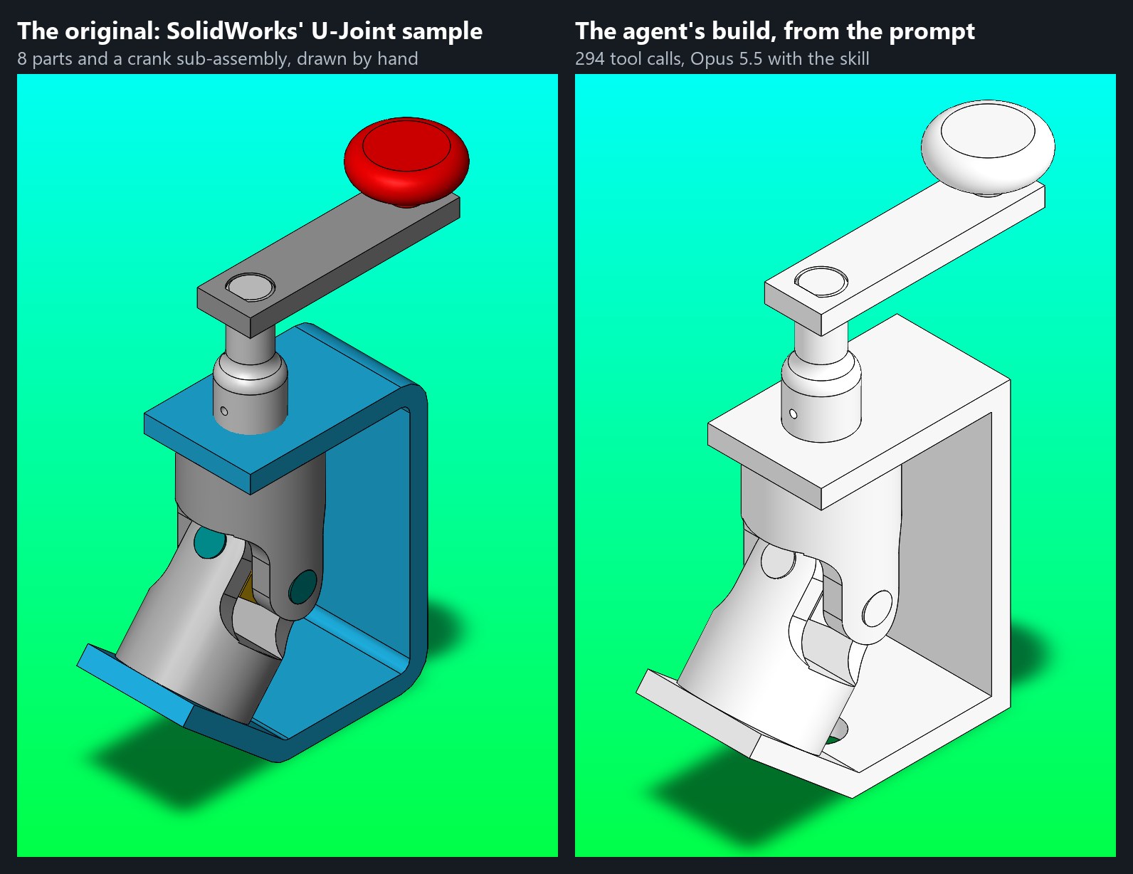
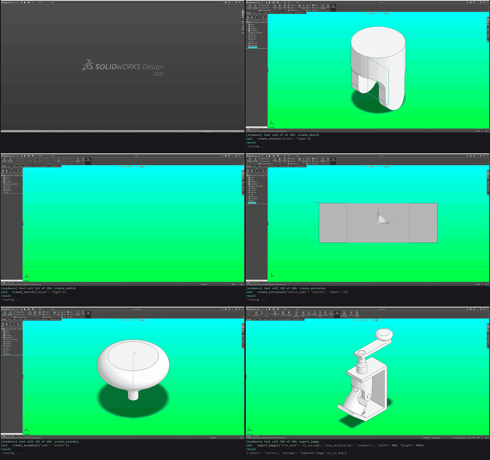
Six of the eight parts match the sample's volume within 0.2 %, and all eight within 1 %. The mates leave the mechanism free to turn. The recording replays the session's 294 calls (sped up 80 times). The walkthrough has the prompt, the part-by-part comparison, and what the agent couldn't do. The same prompt run with and without the agent skill made the same parts, which is why I want skills that improve results (#207).
A drawing package from one prompt
Make a 100 x 50 x 10 mm AISI 1020 mounting plate with four M5 clearance holes, 10 mm in from each edge, and draw it fully dimensioned. Stack two of them 10 mm apart, check the result, and draw the assembly with a BOM.
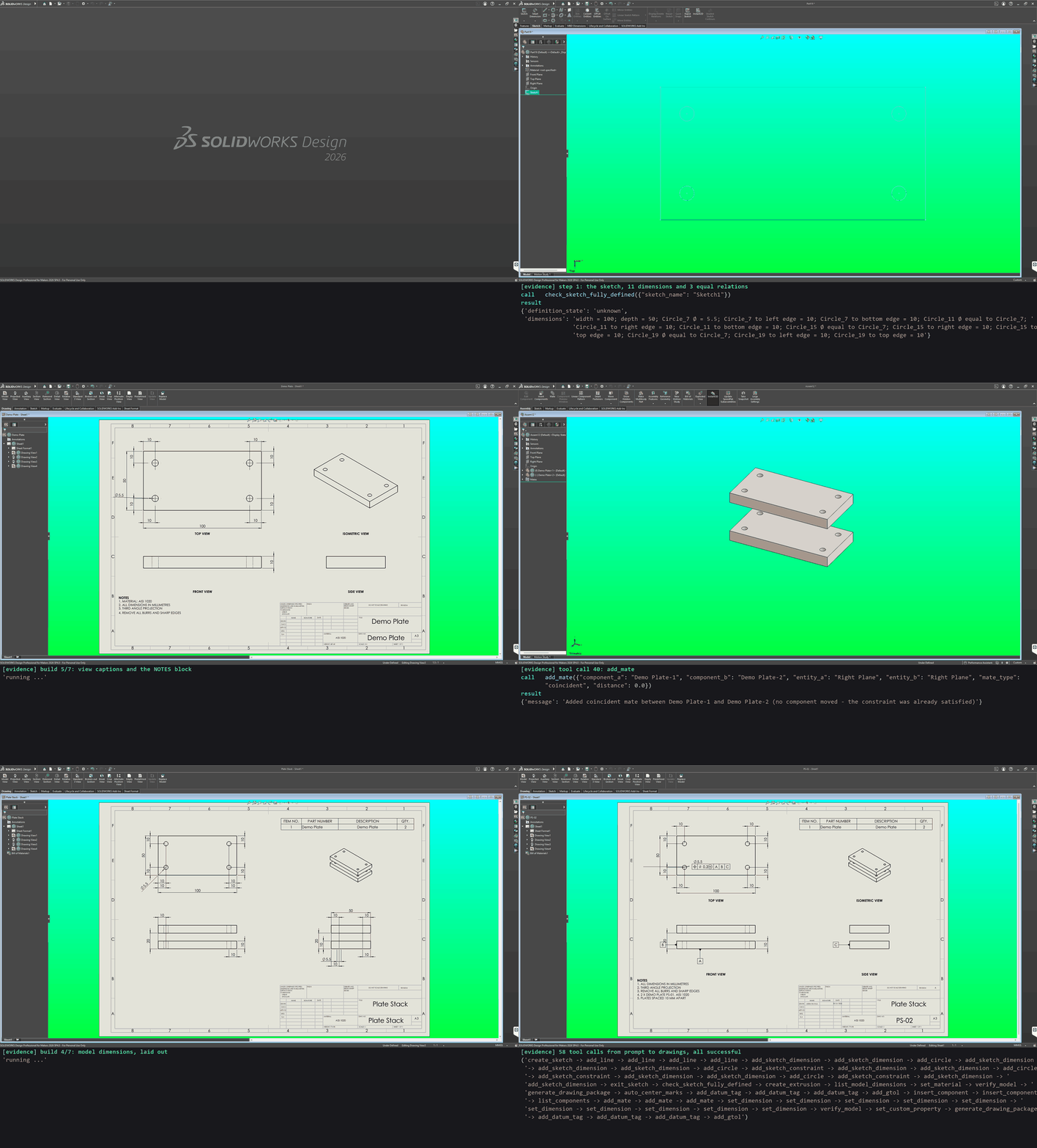
The 58 tool calls an agent made from that prompt, run against SolidWorks 2026 through the same MCP tools a client calls, and recorded (sped up five times). Each result is checked against a hand calculation: the plate's volume and mass, the 10 mm gap and the BOM quantity. This is a replay of the calls, not a recorded model session.
Note: the demo is not perfect, and is not the most efficient way to get this result. The run pauses after each call so it can be read, and the calls are chosen to show what the tools can do: every sketch dimension is added one at a time, and the mate distance is stepped down only so the plates are seen coming together.
The walkthrough in the docs has the agent's plan and every call with its arguments. Run it yourself with the README demo; the calls are also in plate_stack_calls.json.
- Sketch (24 calls):
create_sketchon Top; fouradd_linefor the 100 x 50 outline;add_circlefor each Ø5.5 hole;add_sketch_dimensionfor the 100, the 50, one Ø5.5 and each hole 10 mm from two edges;add_sketch_constraintmaking the other three holes equal;exit_sketch - Check and extrude:
check_sketch_fully_defined,create_extrusion10 mm (+49 049.7 mm³ read back) - Material and check:
list_model_dimensions(finds the Ø5.5 by value),set_materialAISI 1020,verify_model(volume, mass 0.3875 kg, size, 1 feature, 1 body) - Plate drawing:
generate_drawing_packagePS-01 (A3, four views, every model dimension laid out with no overlaps, notes, title block, PDF),auto_center_marks - GD&T:
add_datum_tagA, B and C, thenadd_gtol⊕ Ø0.2 Ⓜ A|B|C on the Ø5.5 - Assembly:
insert_componenttwice,list_components,add_mateFront and Right coincident and Top planes 60 mm apart,set_dimensionstepping that distance down to 20 mm (10 calls),verify_model(2 parts, 3 mates, no interference; the stack measures 30 mm, so the gap is 10 mm) - Assembly drawing:
set_custom_propertyMaterial,generate_drawing_packagePS-02 withinclude_bom(the BOM above the isometric: Demo Plate, QTY 2), then the same datums and position frame
Overview
Tried it? Tell us what worked and what didn't in a feedback issue. Reports from real setups decide what gets fixed next.
This project focuses on practical SolidWorks automation with an AI-friendly loop:
- describe intent
- generate a plan
- execute MCP tools
- inspect results
- iterate
It includes:
- core MCP runtime for SolidWorks tool execution
- COM/VBA routing and adapter safety wrappers
- tool coverage across modeling, sketching, drawing, analysis, export, automation, templates, and macros
- optional agent orchestration/testing utilities under
src/solidworks_mcp/agents/
Demos
Each GIF is a live test driving SolidWorks 2026 through the MCP tools, with the call and its result captioned beneath. Click one to see what it checks, a prompt that asks for it, and its tool calls.
See every demo in the docs: what each one shows, its prompt, every tool call with its arguments (all 58 for the demo at the top), and how to run them yourself.
Supported Today
- Windows + SolidWorks COM automation for the main CAD lifecycle.
- Tested on SolidWorks 2026. Earlier versions may work but are untested. To check yours, run
uvx solidworks-mcp-python selftestwith SolidWorks open, then send the result with the compatibility report form. The compatibility page lists the releases checked so far. - Modeling, sketching, drawing, analysis, export, automation, templates, and macro tools.
- Every tool's support level, and the reason a tool isn't stable yet, is on the progress page.
Not Yet / Simulated
- Mock adapter output is simulated and should not be treated as engineering truth.
- Live 3D viewport streaming in a UI.
- Checkpoint-level interference validation.
- Simple simulation and fluid workflows
- Simple Topology Optimization via SimulationXpress etc.
Install
You need Windows 10 or 11 and SolidWorks (opened at least once). In PowerShell, install uv, then open a new PowerShell window and run setup:
powershell -ExecutionPolicy ByPass -c "irm https://astral.sh/uv/install.ps1 | iex"
uvx solidworks-mcp-python setup
uv fetches Python 3.13 and the server from PyPI by itself; nothing to clone. The guided setup then:
- finds your SolidWorks version and the MCP clients on your PC: Claude Desktop, Claude Code, VS Code, Cursor and LM Studio;
- lets you pick which clients to connect;
- starts the server once to check that it lists its tools (in mock mode, so SolidWorks isn't touched);
- adds a
solidworksentry to each client you picked, then tells you what to restart.
Nothing needs a login or an API key, and the server runs only on your PC. Setup changes only the solidworks entry in each client's config. It backs the file up first and never shows or changes your other servers. Other entries that start this server the old way (run-mcp.ps1 and the like) are offered for removal, so tools don't load twice.
To check it worked: open SolidWorks, restart your client, and ask "What model is open in SolidWorks?"
The package is solidworks-mcp-python. uvx solidworks-mcp installs a different project. To work on the server itself, install from a clone. More fixes are in Troubleshooting.
Вопросы о SolidWorks MCP
Как добавить SolidWorks MCP в Claude Code?
Выполните claude mcp add solidworksmcp-python -- uvx solidworks-mcp-python в терминале. Добавьте --scope user, чтобы сервер был доступен во всех проектах.
Как добавить SolidWorks MCP в Cursor?
Откройте ~/.cursor/mcp.json и добавьте сервер в mcpServers, используя конфигурацию Cursor из раздела установки выше.
Что этот сервер может делать в SolidWorks?
Он позволяет ИИ-агентам создавать детали, сборки и чертежи на основе текстовых описаний, а также выполнять операции выдавливания и управлять сопряжениями.
Можно ли использовать это без ИИ-агента?
Да, сервер предоставляет Python-интерфейс для прямого управления SolidWorks с помощью асинхронных вызовов Python.
Сколько инструментов доступно?
Сервер предоставляет 156 MCP инструментов для автоматизации SolidWorks.